If I were ever stranded on a deserted island and had the freedom to bring one person to maximize my chances of escaping, it would probably be my dear friend Oskar. Like a chaotic scientist, he has a talent for assembling all sorts of components he finds lying around to create the most incredible devices. These include blinking RGB glasses, theme party props, and hoverboards with a dangerously high number of battery cells. I wouldn’t be one bit surprised if he managed to build a satellite dish out of coconuts and sticks to send an emergency signal from the little island.
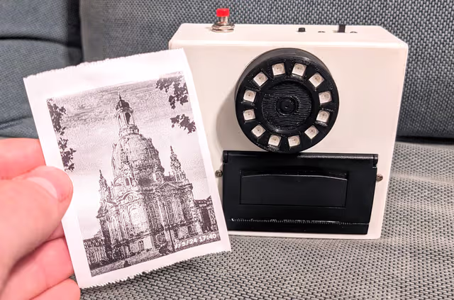
In March 2023, he presented his latest invention: a camera with a self-designed and 3D-printed case that featured a thermal printer.
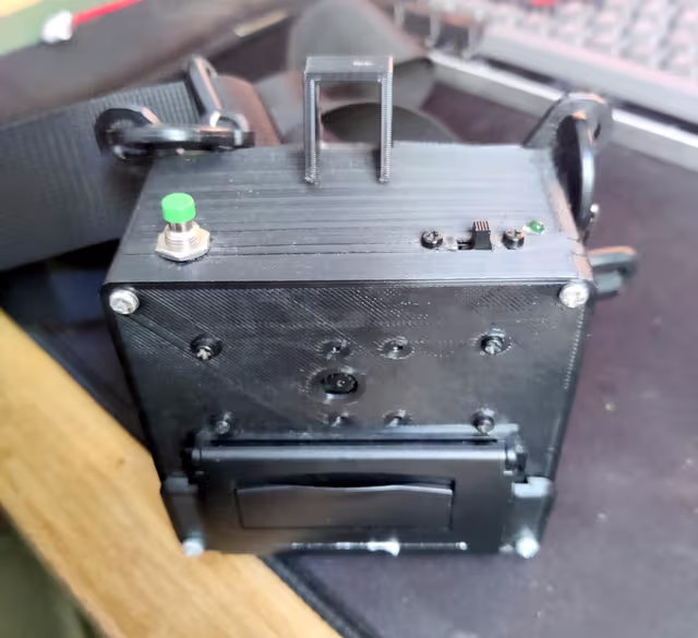
Without a viewfinder, it was always an experience waiting in anticipation for the picture to slowly print out, accompanied by the rattling sound of the thermal printer, giving it the vibe of a Polaroid camera. At the same time, depending on the thermal paper rolls you buy the cost per picture comes down to something between 2 and 5 cents. Ripping the picture off like you would a receipt is also extremely satisfying.
Oskar’s inventiveness inspired me, and I finally found a project that motivated me to start soldering electronic parts together. From the very start, it was clear that this would be a large and expensive project. However, I am generally much more motivated when the end result is not just a learning experience but also something practical that I can use in my daily life and show off.
List of required items
In the following I provide a list of tools and components that were necessary to build the Oskam. I personally did not buy it a batch, as I realized with many components only later on that I even need them. This was also a big reason why this project took me 3 months to complete.
Necessary Tools
- Soldering Iron
- Hot-Melt Gun
- Phillips screwdriver
- Micro SD Card adapter
Components
| Component | Price |
|---|---|
| Shutter Button | 2.46€ |
| Real Time Clock Module | 2.85€ |
| LIR2032 Li-Ion chargeable Button Cell | 1.85€ |
| 128x64 OLED Display | 5.29€ |
| 4 Button Keypad | 1.19€ |
| 12-Bit LED Ring | 1.54€ |
| Jumper Cables | 3.66€ |
| Powerbank (used as battery) | 12.99€ |
| Slide Switch | 2,90€ |
| Camera Module | 8.99€ |
| Shrink Tubing | 5.99€ |
| Mini Thermal Receipt Printer (2752) | 42.25€ - DISCONTINUED |
| Tactile Button (474-COM-12992) | 0.55€ |
| USB C Breakout Board | 6.99€ |
| Raspberry Pi Zero | 17.90€ |
| SD Card | 10.99€ |
| Thermal Printing Rolls | 9.99€ |
| PCB Spacer Standoff & Screws | 6.94€ |
| 145.32€ |
The Thermal Printer has been discontinued, but there are some alternative sites to get them from, for example Alternative Alibaba Link or Ebay
Please note that some of these components were purchased on sale, so prices can vary significantly. Additionally, you’ll need to consider the cost of printing the case, which I could do for free at my university.
The total comes to 145.32€ excluding shipping costs and the expense of printing the case.
Case Design
Designing the case was one of the most challenging tasks. It required fitting all the components in as little as possible volume, while still making it maintainable. It needed to have a handy size, so you could hold it and press the shutter with just one hand. Another challenge was scaling the standoffs, that I would put the components on, even more so given the fact that 3d printers come with a certain tolerenance when printing. As someone who has never constructed complex 3D models this was intimidating.
First I was scouting possible case designs on Pinterest and the likes, looking for old polaroid cameras. Then I drew some sketches, That would help me when constructing the case:
I first though about using Blender, as I already had some experience with it. But designing the case using blender had the major downside, that it would bake all changes into the model, making it tough to change the design later on.
As I was already prepared to go through multiple design iterations, I instead decided to go for a parametric 3D modeling and computer-aided design (CAD) software. It’s particularly useful for engineering and mechanical design work, offering precise modeling tools and parametric capabilities that allow users to define and modify designs with great accuracy. I could have used Fusion360, which is provided for the duration of my studies by my university. I decided against it, as starting from zero, it seemed more beneficial to learn a software I could use even after my studies are finished. I opted for FreeCAD, an open-source parametric 3D modeling software designed for engineering and mechanical design tasks.
The design consisted of 3 different parts:
In total it took me 3 tries to finally get the case to both fit the parts and to get it down to a handy size. The case (without the objective lens) has the measurements 10.2cm x 9.7cm x 4.9cm (whd). After coloring the buttons with acrylic paint, I used varnish from a spray bottle to seal it against dirt.
Software
To code on the camera I used MobaXterm, that features comfortable SSH access, easy file transfer and a gui editor with automatic file save.
A very important part for me was including a small display and a few buttons, as this would allow me to provide a way for users to tweak settings as well as using the camera for other features. The display could also be used to show the user a preview of the image they are taking, effectively working as a viewfinder. Seeing the image before it gets printed takes away some of the fun, which is why I opted for a tiny 128x64 OLED Display. This allowed for basic navigation and features, but is not too distracting or energy consuming.
I used object-oriented programming for the logic of the screens, that get put on a stack when entering, yielding hierarchical navigation pattern:
class ScreenInterface:
  """ Push another screen on top """
  push = None
  """ Pop the current screen """
  pop = None

  def __init__(self, push, pop):
      self.push = push
      self.pop = pop

  def print_screen(self) -> void:
    """Print the screen onto the display (display variable is
    available globally)"""
    pass

  def update(self, key: str) -> void:
    """ Update the screen depending on the pressed key """
    pass

  def release(self) -> str:
    """ Perform cleanup of used resources before the screen is
    destroyed """
    pass

  def pause(self):
    """ Called when another screen is put ontop, so that
    resources usage can temporarily be paused """
    pass

  def resume(self):
    """ Called after a screen that was on top is released, so
    that resources usage can resumed """
    pass
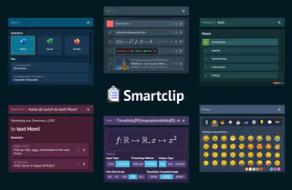
In the following picture you can see all the different screens
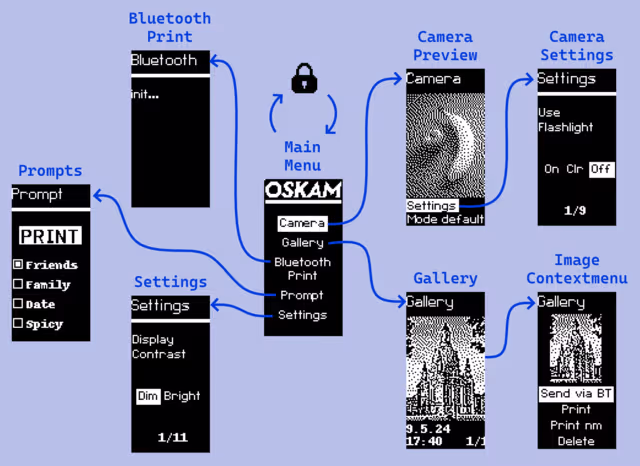
In all of the states this shutter button will take an image. The images are also saved digitally. The camera takes quite some time to boot, which is why I often powered it on and left it, so that I would be able to make snapshots. Unfortunately, this caused the camera to print several all black pictures when I did this during a bike tour at the baltic sea, keeping it in my backpack. To counteract this, I implemented a lock state. Going back from the main menu first powers off the display, pressing back again locks the camera. In this state, the camera can only be turned on again by pressing the enter and the shutter button simultaneously.
Camera Preview
This shows a small preview of the camera with relatively low framerate. Using the picamera2 API this required me to implement a custom preview, that would run in another thread, handling incoming image data. As there was barley any documentation on how to do this, this was rather complicated. The preview images are not preprocessed, so if there is low contrast in the image, there will be barely anything visible on the screen. However, to find the right boundaries for the image it proved sufficient.
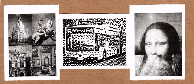
The camera also features different modes, that again aren’t hardcoded but can be provided as classes that implement an process_picture(self, image) function and have a description property. Currently, there are three modes besides the default mode:
- 2x2: Take 4 pictures before the camera prints a 2x2 collage of the images, perfect for taking photos with your friends
- pixelated: prints the picture as seen on the OLED screen - heavily pixalated
- two face: take 2 photos, the camera takes the upper half of one photo and the lower half of the other and fuses them together
Camera Settings
Thought the Camera Preview you can also access the camera settings, most of which are used even when taking images outside of the preview mode. As with the settings these are provided as a JSON object, so that settings are easily extensible.
- Use Flashlight: On, off, and colored flashlight - I barely ever use this option
- Use Nightmode: Whether to use the image postprocessing as described in another blog post, basically always in use
- Print Images: Whether to print images after being taken, as sometimes you don’t need the printed version. Also useful for testing!
- Print Date/ Time: Whether to print date and time onto the image - funny enough I implemented this before realizing I would need a Real Time Clock module for this 😅
- Printing Size: Printing in sizes L, M and S, where L is default (approx. 4.8cm x 6.5cm without the white border) and S is just a small preview used for testing
- Timer: Timer that can be set to 6 and 10 seconds. After pressing the shutter button the LED ring around the lens is used as a loading indicator
- Feed Paper after Printing: Whether to feed paper after a picture is printed. Can be turned off to print multiple pictures next to each other without padding.
- Feed Paper: For manually feeding paper after printing
- Save taken Pictures: Whether to save digital copy of the taken picture
Gallery and Image Context Menu
Used for showing taken pictures with their date and time and printing them again. They can be printed both “normally” or with the Illumination postprocessing enabled. Pictures can also be sent via Bluetooth, although this sometimes is buggy. It is also possible to delete pictures.
Bluetooth
Speaking of bluetooth, what would a good computer science project be without some bluetooth (the 2000s called). However, it is not only possible to receive taken pictures via bluetooth on your smartphone; you can also print pictures from your smartphone using the Oskam. The bluetooth handler is running in a separate thread and gets killed when the Bluetooth screen is closed. It is also possible to send commands to the Oskam (for example by using Serial Bluetooth Terminal app from the Play Store). I implemented this so that I would be able to set a title using bluetooth and printed images would get the title printed beneath them, like “vacation to the lagune”. I never ended up using this though. Maybe there are other applications?
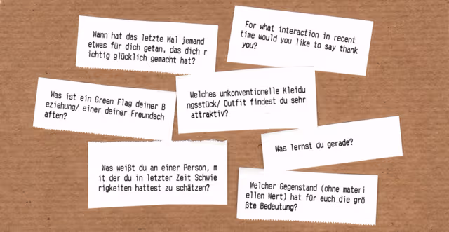
Prompts
On a nice bar evening I played Vertellis, a card game featuring questions to get to know each other better, together with friends. I realized how fun and intimate talks can be and how often I was thinking about interesting questions to ask people, never when being with people though. I started noting down the questions I came up with in a WhatsApp chat and later transfered them into a JSON file. As I spent so much time with some people, the ~160 questions weren’t enough anymore I added questions from different websites into the mix. I called these questions prompts and put them in different categories, based on the group you are playing with.
I implemented the Prompt screen to print out a random prompt out of the selected categories. The rules are mostly up to you. If you don’t like the question, just print another.
The response to them has been rather mixed. Some people love them, some friendships broke over them. I can say I got to know people on a whole different level and now know a lot of funny and interesting stories and details about them.
Settings
As with the camera settings this screen is produced based on a provided JSON object, allowing for easy extensibility. It features the following settings:
- Display Contrast: Dim or Bright display contrast
- Start with Display off: Whether to start the camera with display off
- Toggle Torch: Toggle the LED ring lights, using it as a torch
- Toggle Rainbow: Toggle the LED ring lights, going through all the color hues, using it as an ambient light. This requires another thread to run.
- Archive Photos: Archives taken pictures, moving them to another folder, so they wont be visible in the gallery anymore. Initially implemented because I thought I would just leave all the pictures on the camera, but I ended up just deleting them on the Oskam after backing them up
- Reset Title: Deleting the title that can be set using the Bluetooth screen
- Only my Prompts: Whether to use Prompts from all sources or only those that I came up with
- Wifi: Turns on the Wifi, that is normally turned off to save time when starting up
- Shutdown now: Shuts down the Raspberry Pi Zero board. This still requires using the slide switch to turn off the power supply, as the printer is powered separately.
Notes
I used suggestions from a post on Raspberry Pi Geek to optimize the boot time. Doing this I turned of Wifi and Bluetooth by default.
Unfortunately, there once was a bug in my implementation and the camera would start up the Python script, making it impossible to turn on the Wifi using the settings. After having to solve this by taking out the SD card (which in my case was pretty complicated, as many things are glued together) I implemented error handling that turns on Wifi if an error occurs.
I also needed to reset my router due to an issue with my provider once, and the camera wouldn’t automatically connect to the Wifi in my apartment anymore. For these cases I also saved access to my phone hotspot, which came in quite handy often.
I tried three different kinds of thermal paper rolls. The best ones so far are from Amazon. They feature high quality, have a glossy finish and are more resistant to stain from the sunlight than others that I’ve used.
You can find a list of the installed PIP modules with their version here (pip list).
Cable management
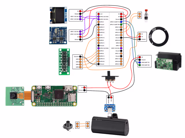
Notes
- Please note that the Universal asynchronous receiver-transmitter (UART) protocol requires the RX pin of one device to be connected to the TX cable on the other device and vice versa. As someone who has no clue about the protocols used by the electronic components, it took way too much time to realize this—once again Oskar came to the rescue.
- I didn’t solder the USB C Breakout Board, so that the power bank, that the Oskam uses as a battery, can still be used as a power bank in emergency situations.
- Due to the limited space I stripped the powerbank of its case. Be careful when doing this as batteries can explode when there is force applied to them. It also turned out that the power bank only turns on when either a device is physically connected or when a button on the power bank is pressed. Because of this, I needed to add another button to the Oskam that needs to be pressed after using the slide switch to deliver power.
- connecting 2 I2C components proved a little annoying. Feel free to reach out to me if you are having trouble with this.
Pictures from Inside
Result